close
Choose Your Site
Global
Social Media
Views: 0 Author: Site Editor Publish Time: 2026-08-24 Origin: Site
Modern heavy-duty diesel engines rely on highly complex aftertreatment systems to stay on the road. A single sensor failure within this network can quickly trigger severe engine derates or costly fleet downtime. The selective catalytic reduction (SCR) system never injects Diesel Exhaust Fluid (DEF) blindly into the exhaust stream. Instead, it relies entirely on real-time emissions data from the NOx Sensor to calculate precise dosing requirements. Without accurate feedback, the engine control module cannot neutralize harmful gases effectively.
This article explains the critical data-to-dosing feedback loop driving modern emissions control. We will highlight the financial risks associated with inaccurate sensor readings. You will also learn a proven framework for evaluating and sourcing reliable replacement parts. This knowledge helps fleets streamline maintenance, reduce diagnostic confusion, and prevent frustrating repeat failures across commercial vehicles.
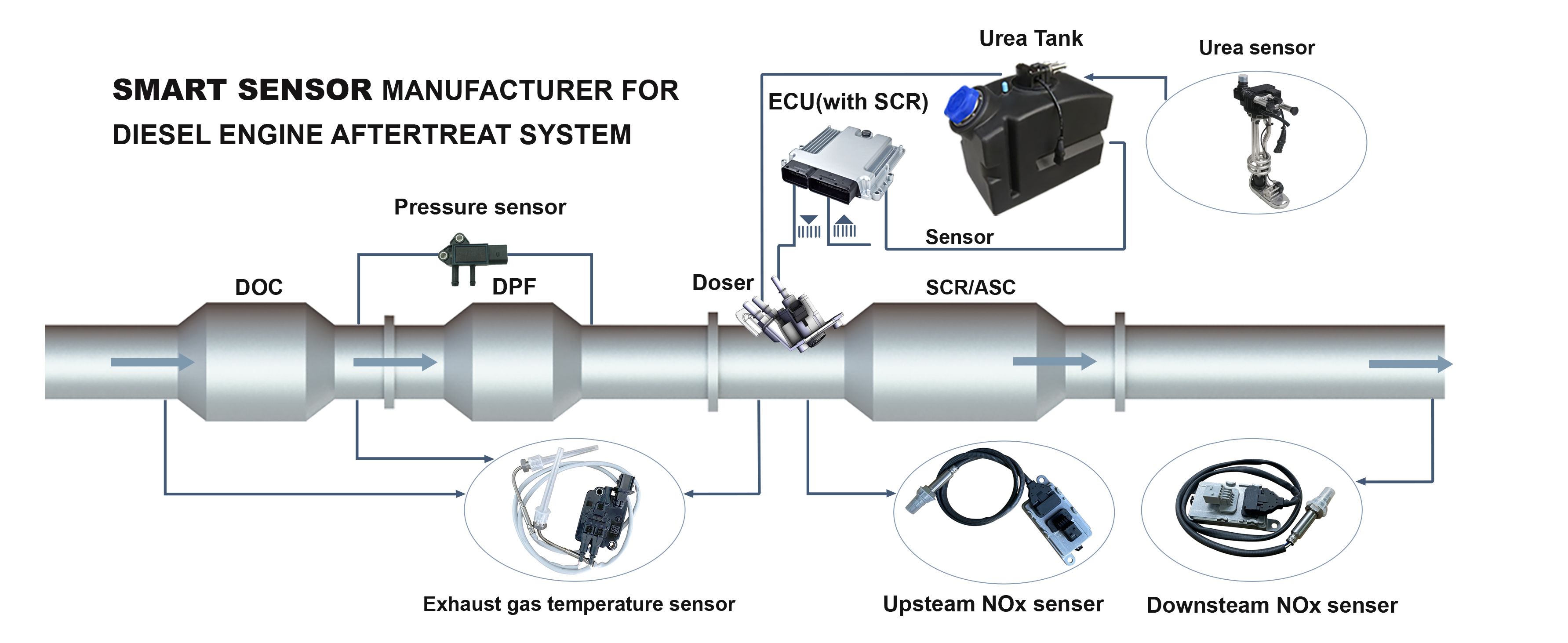
Data-Driven Dosing: The upstream and downstream NOx sensors create a closed-loop system, dictating exactly how much DEF the doser injects to neutralize emissions.
The Cost of Inaccuracy: Sensor degradation leads to over-dosing (causing DEF crystallization and hardware damage) or under-dosing (resulting in compliance failures and immediate engine derates).
Evaluation Criteria: Replacing a diesel NOx sensor requires assessing ceramic element quality, communication speed (CAN bus integration), and proven compliance with EPA standards.
Diagnostic Pre-requisites: Replacing the sensor without verifying DEF fluid quality or checking baseline PPM readings often leads to repeat failures.
Fleet operators often view emissions sensors as simple compliance devices. However, they act as the financial gatekeepers of your aftertreatment system. The DEF doser acts strictly on commands from the Aftertreatment Control Module (ACM). This module relies entirely on continuous inputs from emissions sensors. When these inputs drift out of calibration, the financial consequences multiply rapidly.
We must understand the dual risks of sensor degradation. A skewed reading artificially inflates or deflates DEF demand. Both scenarios severely damage fleet profitability.
Sometimes, a faulty sensor reports higher emission levels than actually exist. The ACM responds by commanding the doser to spray maximum fluid into the exhaust stream. The extreme heat cannot vaporize this excessive liquid volume fast enough. As a result, the unvaporized urea crystallizes inside the decomposition tube. This hard white buildup eventually plugs the face of the SCR catalyst. Exhaust backpressure spikes rapidly. You will face premature hardware failure, forcing a catalyst replacement that costs thousands of dollars.
Conversely, a degraded probe might under-report harmful gas levels. The system believes the exhaust is cleaner than it truly is. It scales back DEF injection accordingly. Un-neutralized pollutants then pass through the tailpipe. The downstream monitor detects this failure immediately. It pushes the vehicle out of EPA emissions compliance. The engine control unit (ECU) then triggers hard derate codes. The truck will eventually lock into a five-mile-per-hour crawl, grounding the asset completely until repairs occur.
Replacing a failed component is only half the battle. A truly successful repair restores the accurate baseline Parts Per Million (PPM) measurement. Accurate measurements optimize fluid usage. They also prevent downstream catalyst poisoning. Fleet managers must prioritize sensor accuracy to protect the broader mechanical ecosystem.
Common Mistake: Technicians often clear the dashboard fault codes without verifying actual fluid consumption rates post-repair. Always monitor injection volumes during the first test drive.
To diagnose faults correctly, technicians must understand the mechanical logic governing the doser. The entire process functions as a continuous feedback loop. It requires precise synchronization between physical hardware and digital sensors.
The process begins right after exhaust gas exits the Diesel Particulate Filter (DPF). The inlet probe measures raw engine-out emissions before any chemical treatment occurs. This reading gives the engine control module its primary data point. The computer uses this baseline to calculate the exact fluid volume required to trigger a successful chemical reaction. Without this initial baseline, the system would merely guess at required injection rates.
After the fluid mixes with the hot exhaust gas, it converts into ammonia. This ammonia enters the catalyst and neutralizes the harmful gases. Finally, the outlet SCR NOx sensor measures the remaining tailpipe emissions. It verifies the overall conversion efficiency of the system. If the outlet reading drops below acceptable EPA thresholds, the system knows the chemical reaction succeeded.
The ECU constantly compares the upstream and downstream data. It calculates the delta between the two figures. If the downstream reading climbs too high, the computer instantly increases the injector pulse width. It commands more fluid into the stream. If the downstream reading drops near zero, the computer reduces injection pressure to save fluid. This dynamic adjustment happens multiple times per second.
System Diagnostic Summary Table
Sensor Location | Primary Function | Data Action Triggered by ECU |
|---|---|---|
Upstream (Inlet) | Measures raw engine-out exhaust gases | Calculates initial DEF injection baseline |
Downstream (Outlet) | Measures tailpipe conversion efficiency | Adjusts fluid dosing up or down in real-time |
System Delta | Compares inlet vs outlet values | Validates overall catalyst health and compliance |
We must note one critical assumption regarding this mechanical logic. This data-driven process assumes the physical DEF doser and the catalyst itself are in perfect working order. A pristine sensor cannot fix a mechanically clogged sprayer nozzle. The electronics can only guide functional hardware. You must rule out physical blockages before replacing electronic monitors.
When a probe fails, procurement teams face a flooded aftermarket. Not all replacement parts offer the same durability or accuracy. You must evaluate several technical criteria to ensure you install a dependable component.
Component Quality and Ceramic Elements: Focus heavily on the internal materials. The core of the device features a zirconia ceramic element. This probe must withstand extreme exhaust temperatures exceeding 800 degrees Celsius. It also faces constant bombardment from abrasive soot particles. High-grade ceramic maintains calibration despite these harsh conditions. Inferior ceramics crack under thermal shock, leading to immediate failure.
PPM Accuracy Tolerances: Evaluate the required precision of the unit. High-quality parts must provide exact PPM readings that align perfectly with OEM specifications. Even a five percent drift in accuracy causes false dosing commands. Strict manufacturing tolerances prevent the ECU from overworking the fluid pump.
CAN Bus Communication Speed: Assess the processing chip inside the rectangular control module. The probe detects gases chemically, but the module translates this into a digital signal. It must relay data over the J1939 CAN bus network instantly. Communication lag results in delayed injection and sudden emission spikes during hard acceleration.
Compliance and E-E-A-T: Always select components manufactured to meet stringent EPA10 (or newer) regulations. Avoid unverified, ultra-low-cost alternatives found on generic marketplaces. These parts often lack proper factory calibration. They risk non-compliance and often trigger ghost codes that frustrate your diagnostic technicians.
Best Practice: Always ask your supplier if their parts undergo automated end-of-line testing. Validated parts provide better peace of mind for heavy-duty applications.
Even the highest-quality replacement part will fail if technicians ignore basic diagnostic realities. You must prepare the vehicle properly before turning a wrench. Replacing electronics blindly wastes shop hours and parts budgets.
We strongly recommend testing fluid concentration before you touch the exhaust pipe. Mechanics should use a digital refractometer to check the tank. Proper fluid must contain exactly 32.5 percent high-purity urea. Poor fluid quality drastically lowers conversion efficiency. The system will trigger a fault code. Technicians often falsely blame the diesel NOx sensor for this failure. Always verify fluid chemistry first.
Technicians must interpret baseline data correctly. Do not rely solely on static fault codes. Connect your diagnostic software and monitor the live PPM readings. Run a forced regeneration or test the truck under a heavy load. A healthy outlet probe should show a steady drop in emissions as the catalyst heats up. If the live data jumps erratically or flatlines, the internal ceramic element has drifted out of range.
Installation does not end when you tighten the mounting threads. You must perform a post-replacement reset. Use your scanner to clear all aftertreatment learned values. The ECU adapted its strategy to accommodate the old, degraded part. You must force the computer to relearn the baseline characteristics of the new unit. Run a complete system verification test post-installation to calibrate the fresh electronics with the fluid pump.
Technicians face several implementation risks during installation. Warn your staff against splicing the wiring harness. The cable length is specifically calibrated for electrical resistance. Cutting and soldering wires alters this resistance, ruining signal accuracy permanently. Furthermore, never attempt to clean a degraded probe tip with parts cleaner or compressed air. The delicate internal zirconium layers are highly sensitive to chemical contamination and physical shock.
Procurement choices directly influence fleet uptime. Buying replacement parts requires strategic thinking. You must balance upfront costs against long-term fleet reliability.
Budget constraints often push buyers toward the cheapest available option. However, saving a small percentage on a sub-standard part creates major downstream risks. An inaccurate probe leads directly to thousands of dollars in wasted fluid, expensive towing fees, and lost revenue from stranded cargo. High-quality parts ensure operational reliability. They keep your trucks out of the repair bay and on the revenue-generating highway.
Evaluate vendors based on their post-sale support. Look for suppliers offering comprehensive warranty terms. Ask potential vendors about their historical return defect rates. Furthermore, complex heavy-duty applications sometimes require technical troubleshooting. Choose a supplier who provides accessible technical support when diagnostic questions arise in your shop.
Guide your procurement team to follow strict verification steps. First, locate the stamped part number on the original control module. Cross-reference this OEM number carefully against the supplier catalog. Consult with specialized heavy-duty parts distributors rather than general automotive stores. Specialized distributors validate their replacements for specific commercial engine families.
The electronic monitors in your exhaust pipe serve a critical function. They are not merely passive compliance devices. They act as the active controllers of your entire DEF dosing strategy. The engine control module relies entirely on their real-time feedback to neutralize pollutants safely and efficiently.
Investing in high-accuracy, reliable replacement components protects your commercial assets. Quality sensors prevent dangerous crystallization, optimize fluid consumption, and protect the expensive SCR catalyst from cascading failures. A reliable feedback loop keeps your vehicles moving.
We encourage fleet managers and technicians to review recurring aftertreatment fault codes carefully. Do not let degraded electronics drain your maintenance budget. Consult a trusted supplier catalog today to find validated, direct-fit replacements for your specific engine application.
A: The engine control module loses its emissions feedback loop. It immediately halts fluid injection to prevent catalyst damage. The system defaults to a protective mode, triggering a check engine light. A countdown timer usually begins, eventually forcing the engine into a severe derate (often limited to 5 mph) until the component is replaced.
A: Yes. Diluted or contaminated fluid prevents the chemical reaction inside the catalyst. Because the harmful gases are not neutralized, the downstream monitor reads high tailpipe emissions. The engine computer often flags a sensor failure or low conversion efficiency code, even though the fluid chemistry is the actual root cause.
A: Under a steady-state load with high exhaust temperatures, a healthy outlet probe usually reads between 10 and 50 PPM. However, exact specifications vary significantly by engine manufacturer and operating conditions. During idle or before the catalyst reaches operating temperature, readings will naturally appear much higher.
A: It is highly recommended. Both components endure the same extreme heat, soot exposure, and operating hours. If the upstream unit fails due to age or thermal degradation, the downstream unit is likely nearing the end of its lifecycle. Replacing both simultaneously prevents repeat shop visits and ensures perfectly synchronized baseline data.