close
Choose Your Site
Global
Social Media
Views: 0 Author: Site Editor Publish Time: 2026-10-08 Origin: Site
Modern diesel engines must navigate highly complex emissions regulations worldwide. They rely heavily on advanced Selective Catalytic Reduction (SCR) systems to meet strict environmental standards, including Euro 6 and EPA 10 requirements. However, this compliance architecture introduces unique operational vulnerabilities. A malfunctioning emissions component does far more than trigger an annoying dashboard check engine light. It actively forces commercial vehicles straight into engine derate or limp mode to prevent illegal operation. This sudden torque reduction causes immediate fleet downtime, disrupts supply chains, and results in severe revenue loss.
This comprehensive guide demystifies the precise electrochemical mechanics behind the NOx Sensor. We will explore exactly how they interact within the broader SCR ecosystem. You will also learn practical diagnostic frameworks, real-world failure modes, and the exact engineering criteria you need for evaluating reliable replacement parts.
Dual-Chamber Precision: NOx sensors utilize a sophisticated dual-cavity electrochemical process to separate oxygen from exhaust gas before measuring Nitrogen Oxide levels.
Closed-Loop Control: Upstream and downstream sensors dictate DEF (Diesel Exhaust Fluid) dosing, creating a continuous feedback loop that ensures emissions compliance.
Vulnerability to Environment: Premature sensor failure is rarely an electronic defect; it is most often caused by thermal shock, soot fouling, or DEF crystallization in the exhaust stream.
Procurement Standard: Evaluating replacement sensors requires looking beyond price to assess CAN bus communication stability, ceramic probe durability, and strict OEM-equivalent calibration.
Environmental agencies have aggressively tightened commercial vehicle emission limits over the last decade. The transition from Euro 5 to Euro 6, alongside current EPA regulations, marked a massive paradigm shift. Engines moved from passive emissions monitoring to highly active system intervention.
Early emissions setups merely flagged out-of-spec exhaust gases. Today, engine control units (ECUs) constantly manage tailpipe output in real time. They demand zero-tolerance compliance. If the exhaust stream fails to meet specific clean air thresholds, the ECU acts immediately. It protects the environment by limiting engine power.
You must view the exhaust network as an interconnected factory rather than a simple tailpipe. We call this the Exhaust Aftertreatment System (EATS). A commercial EATS features several vital components working in sequence:
Diesel Oxidation Catalyst (DOC): The first stage breaks down unburned hydrocarbons and carbon monoxide.
Diesel Particulate Filter (DPF): The second stage traps and burns off physical soot particles.
Selective Catalytic Reduction (SCR): The final stage neutralizes harmful nitrogen oxides.
The sensor sits specifically within this final SCR stage. It provides the core data necessary to neutralize toxic gases before they exit the vehicle.
Component failures create immediate business realities. When a sensor breaks, it stops communicating accurate gas levels to the main computer. The ECU assumes the worst-case scenario. It instantly assumes the truck is polluting beyond legal limits.
To enforce compliance, the ECU mandates severe torque reduction. Mechanics often call this "limp mode." Your heavy-duty vehicle might suddenly drop to a 5 mph speed limit. This programmed intervention prevents non-compliant emissions operation. Consequently, sensor health links directly to overall fleet uptime and delivery reliability.
Understanding these devices requires looking past the outer metal shell. We must examine the electrochemical operation happening on a microscopic level. It involves complex chemistry without any marketing fluff.
Exhaust gas enters the probe through microscopic pores. It arrives directly into the first internal cavity. Raw diesel exhaust contains varying amounts of ambient oxygen. This ambient oxygen interferes heavily with accurate nitrogen oxide readings. The sensor must remove it first.
The first chamber uses a specialized Zirconia (ZrO2) ceramic element. The control unit applies a specific pumping current to this ceramic material. The electrical current actively draws ambient oxygen molecules out of the cavity. It essentially purges the sample, creating a clean environment for the next step.
The purified gas sample then moves deeper into the second cavity. Here, the actual measurement takes place. The second chamber contains a dedicated catalytic electrode. This electrode reacts chemically with the nitrogen oxides present in the gas.
The catalytic process forces the compounds to break apart. It reduces the hazardous gas into harmless elemental Nitrogen (N2) and Oxygen (O2). This is a precise molecular dismantling process.
The newly freed oxygen molecules serve a crucial purpose. They interact with the internal circuitry to generate a measurable electrical current. This specific microampere signal represents the core data point.
The strength of this tiny electrical current correlates perfectly with the original gas concentration. We measure this concentration in parts per million (ppm). More nitrogen oxide in the exhaust means more freed oxygen. More freed oxygen means a stronger electrical signal.
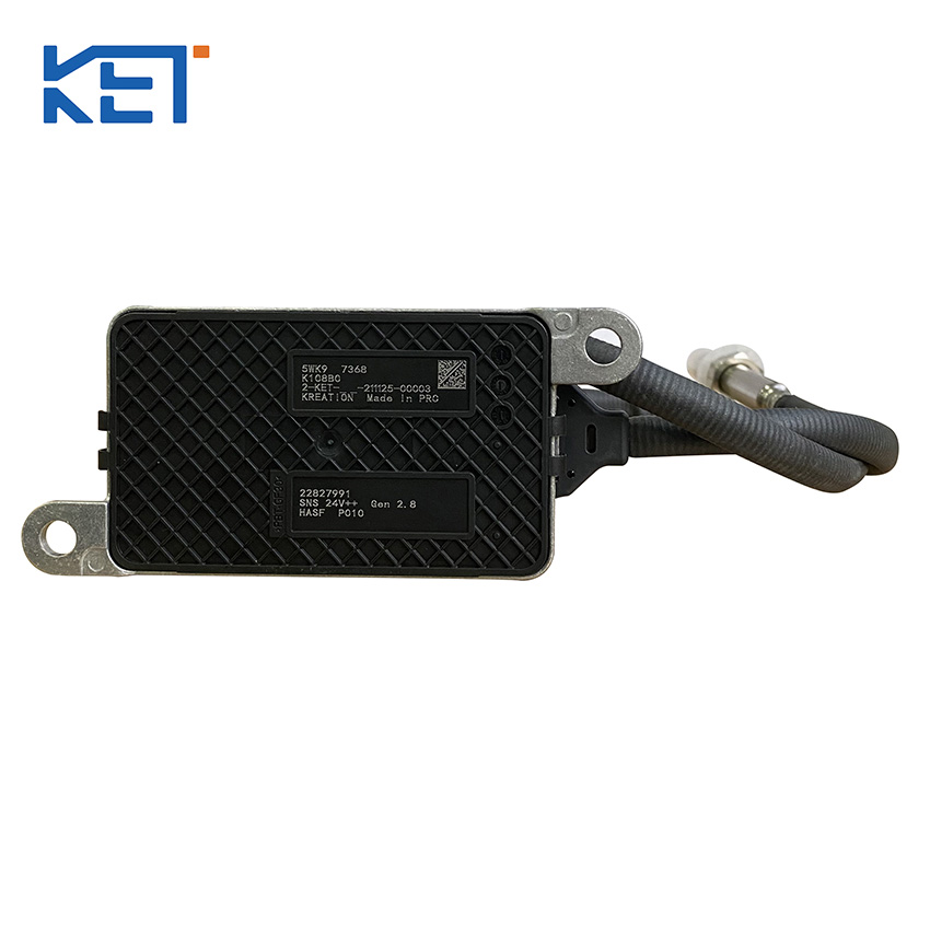
The probe itself cannot speak directly to the engine computer. It requires a translator. Every unit features an integrated microchip housed inside a control module box. This module connects to the probe via a heavily insulated wiring harness.
The microchip receives the raw, analog micro-currents from the ceramic chambers. It instantly translates these analog readings into digital CAN bus signals. The engine ECU easily understands this digital language. It uses this continuous data feed to make split-second operational decisions.
Sensor Probe Functional Stages
Functional Stage | Primary Component | Core Action | Output/Result |
|---|---|---|---|
Gas Entry | Porous Ceramic Shield | Filters physical soot | Allows raw exhaust into probe |
Oxygen Purge | Zirconia Chamber 1 | Applies pumping current | Removes interfering O2 |
Reduction | Catalytic Electrode | Breaks down molecules | Separates into N2 and O2 |
Quantification | Zirconia Chamber 2 | Measures freed oxygen | Generates microampere current |
Data Conversion | Control Module (Microchip) | Translates analog to digital | Sends CAN bus signal to ECU |
Modern aftertreatment architectures rarely rely on a single data point. They use a dual-sensor strategy. This approach creates a sophisticated, closed-loop control network. The network relies on an upstream unit and a downstream unit working together.
The upstream device sits before the SCR catalyst. It measures the baseline raw emissions coming directly from the turbocharger and DPF. This represents the engine's natural exhaust output before any chemical neutralization occurs.
Its primary function is predictive calculation. The ECU uses the upstream data to determine the exact volume of DEF (Diesel Exhaust Fluid) required. It calculates the necessary chemical dosing in real-time. If the engine works hard pulling a load uphill, raw emissions spike. The ECU immediately commands the doser valve to inject more DEF.
The downstream device sits at the very end of the exhaust pipeline. It measures the remaining gases exiting the SCR catalyst. This reading represents the final air quality released into the environment.
Its primary function is strict verification. It audits the efficiency of the entire SCR reduction process. The downstream unit confirms whether the injected DEF successfully neutralized the toxic gases.
These two strategic locations enable perfect closed-loop control. The system constantly compares the upstream "before" picture with the downstream "after" picture. It creates a continuous feedback cycle.
If the downstream unit detects high emission levels, it alerts the ECU immediately. The ECU knows the current DEF injection rate is insufficient. It adjusts the DEF doser to spray more fluid. Alternatively, it alters engine timing to lower combustion temperatures, correcting the chemical imbalance on the fly.
These precise instruments operate in incredibly hostile environments. Premature failure happens frequently. However, the root cause rarely involves electronic defects. Environmental factors cause the majority of physical breakdowns.
Diesel engines naturally produce soot. Incomplete combustion creates heavy carbon deposits. Over time, these thick deposits coat the microscopic protective layers of the internal probe.
This carbon buildup blinds the electrochemical chambers. The porous ceramic material becomes clogged. The exhaust gas can no longer reach the internal Zirconia elements. The device begins sending erratic, falsely low, or completely frozen readings to the ECU. Regular engine maintenance prevents excessive soot production.
Temperature fluctuations destroy ceramic materials quickly. The internal elements heat up to roughly 800°C (1472°F) during normal operation. This extreme heat facilitates the necessary chemical reactions.
Vulnerability occurs when liquids strike this intensely hot ceramic. If cold exhaust condensation hits the probe, the ceramic can shatter instantly. Similarly, if the DEF doser nozzle malfunctions, it sprays unvaporized liquid directly onto the downstream probe. This thermal shock causes microscopic cracks, permanently ruining the NOx Sensor.
The physical connection between the probe and the engine computer often fails first. Heavy-duty vehicles vibrate violently. These vibrations cause physical chafing along the wiring harness. Exposed wires quickly short out against the metal frame rails.
Additionally, the routing often runs near extreme heat sources. Heat-damaged harnesses melt internal insulation. This causes communication timeouts between the module box and the ECU. The computer registers this drop in communication and immediately triggers a fault code.
Technicians must adopt a logical diagnostic framework. You must differentiate between erratic gas readings and hard communication codes. Erratic readings usually point to physical probe fouling or upstream mechanical issues. Hard communication codes almost always indicate a module failure or broken wiring.
We highly recommend verifying two things before replacing any electronics. First, test your DEF fluid quality using a refractometer. Degraded fluid will not neutralize emissions, causing the downstream unit to trigger a legitimate fault. Second, inspect the doser injector spray pattern. A clogged doser mimics a downstream sensor failure perfectly.